The Game of Life on a PCB
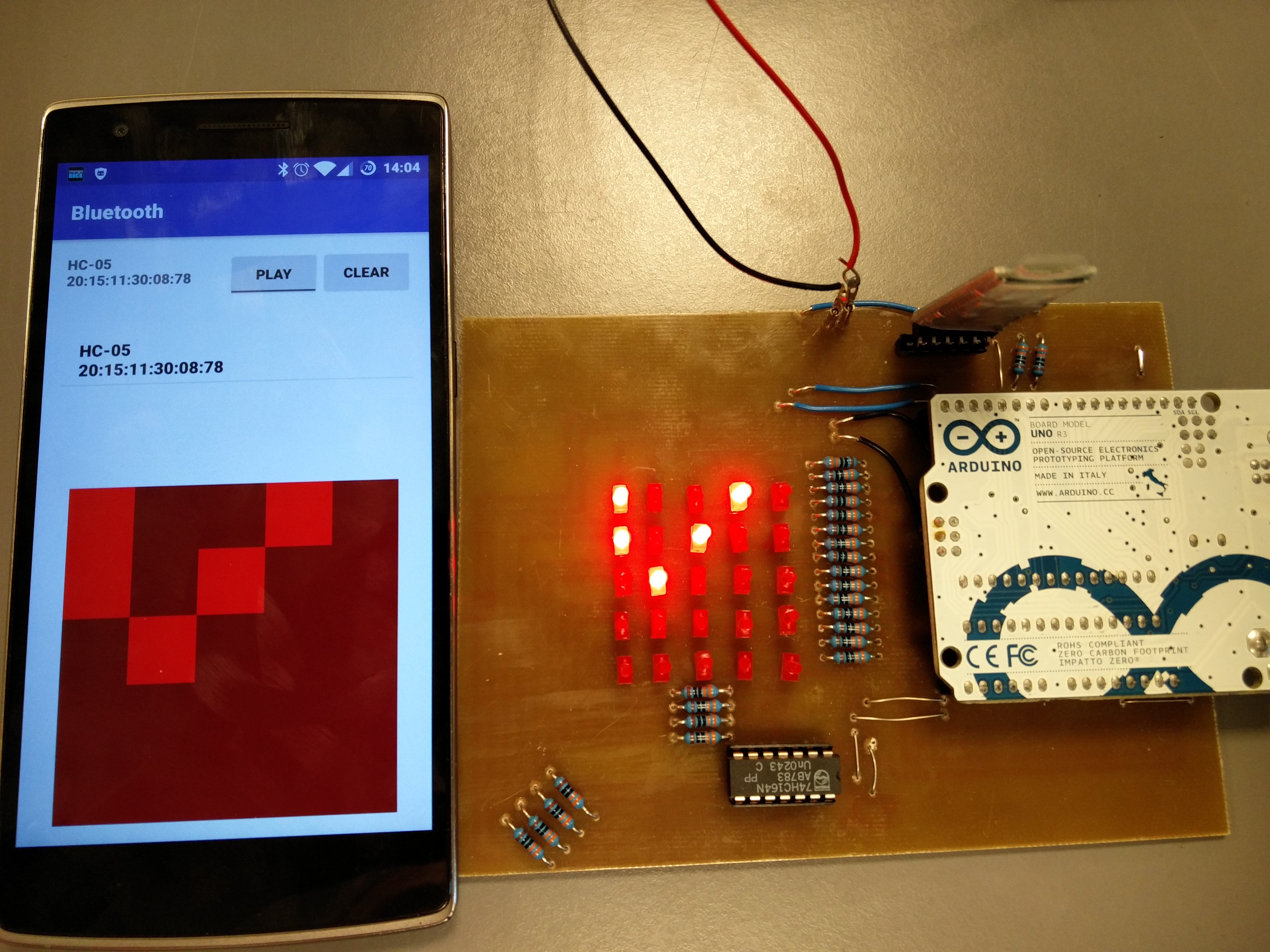
PublishedI've created a printed circuit board (PCB) that simulates the game of life on a 5 by 5 LED grid, and can be remote controlled with Bluetooth. The project was created in collaboration with another student as a school project. Here is a video of the finished product:
What is The Game of Life?
The Game of life is a simulation that runs in a two-dimensional grid of cells. The simulation is run in steps, where the next step depends only on the state of the previous. Each cell in the simulation is either dead or alive in each step.
Rules for computing the next step
The simulation is built from three rules dictating the state of each cell. The state of each cell in the next step, is found by first counting how many of the 8 cells around it are live, and using one of these rules:
- If there are 2 alive neighbours, the state of the cell is not changed.
- If there are 3 alive neighbours, the cell is alive in the next step.
- Otherwise, the cell is dead in the next step.
This is performed on every cell in the grid, and results in the next state. Often when simulating the game of life, the grid is infinitely large, but I don't have that many LEDs, so my grid is just a 5 by 5 grid. There are two ways to handle finite grids: Just let the grid have an edge, or let it wrap around. I've chosen to let the grid wrap around, since this allows me to have a glider, that goes on forever.
The Glider

The configuration shown in the video at the start of the article is called a glider. It is a pattern that moves forever, and is small enough fit in my 5 by 5 grid, without interfering with itself over the edges. This is the best way to show the wrap around in this grid.
Hardware
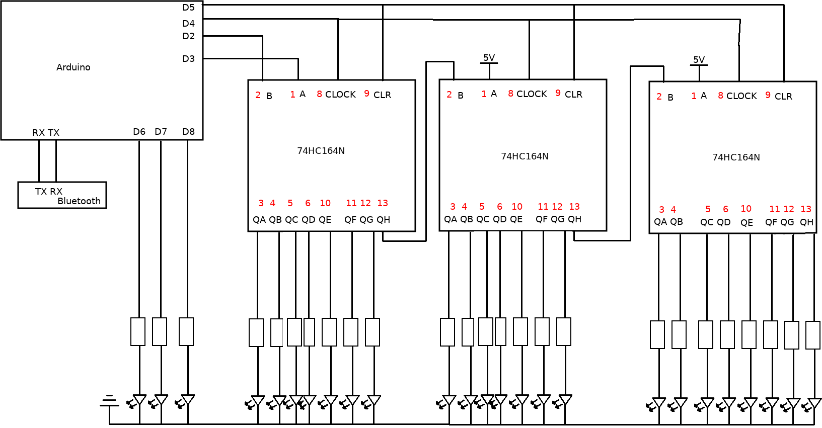
The main challenge in this project is that the Arduino UNO doesn't have enough digital outputs to control 25 LEDs. I solved this problem by adding 3 shift registers, on which I push the state of the LEDs.
What is a shift register?
A shift register traditionally has 2 inputs and n outputs. Initially all the outputs of the shift register are LOW. The first input is called VAL and the second is called CLOCK. Every time the CLOCK input changes from LOW to HIGH, the first output is changed so it's the same as the VAL input, and the second output is changed so it's the same as the first output and so on. Since it takes n updates to the shift register, it allows you to trade ease of updating the outputs for more outputs.
The reason we use a shift register in this project is to control many LEDs with a small amount of outputs from the Arduino. I chain shift registers by connecting the last output from each shift register to the VAL input of the next, which allows me to control all the LEDs connected to the three shift registers, using a small amount of outputs from the Arduino.
In the Arduino code I have an array that maps an LED coordinate to the index in the shift register, which is how the code knows how to control each LED.
The shift register used in this project has a few additional inputs: A, B, CLOCK and CLR. The VAL input I mentioned earlier is split into the inputs A and B, and the VAL input is regarded to have the value true only if both A and B are true. The CLR input just sets all outputs to low.
In order to update the board once, the Arduino has to write to the shift registers 24 times. The reason that it needs to write 24 times, even though 3 LEDs are connected directly to the Arduino is elaborated on in the Imperfections section.
The final design
The shift registers I used are called 74HC164N.
The circuit board is very simple; it just chains some integrated circuits and connects them to LEDs. The resulting layout, which I created from the design above, is shown below:
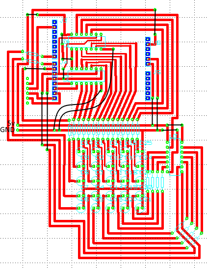
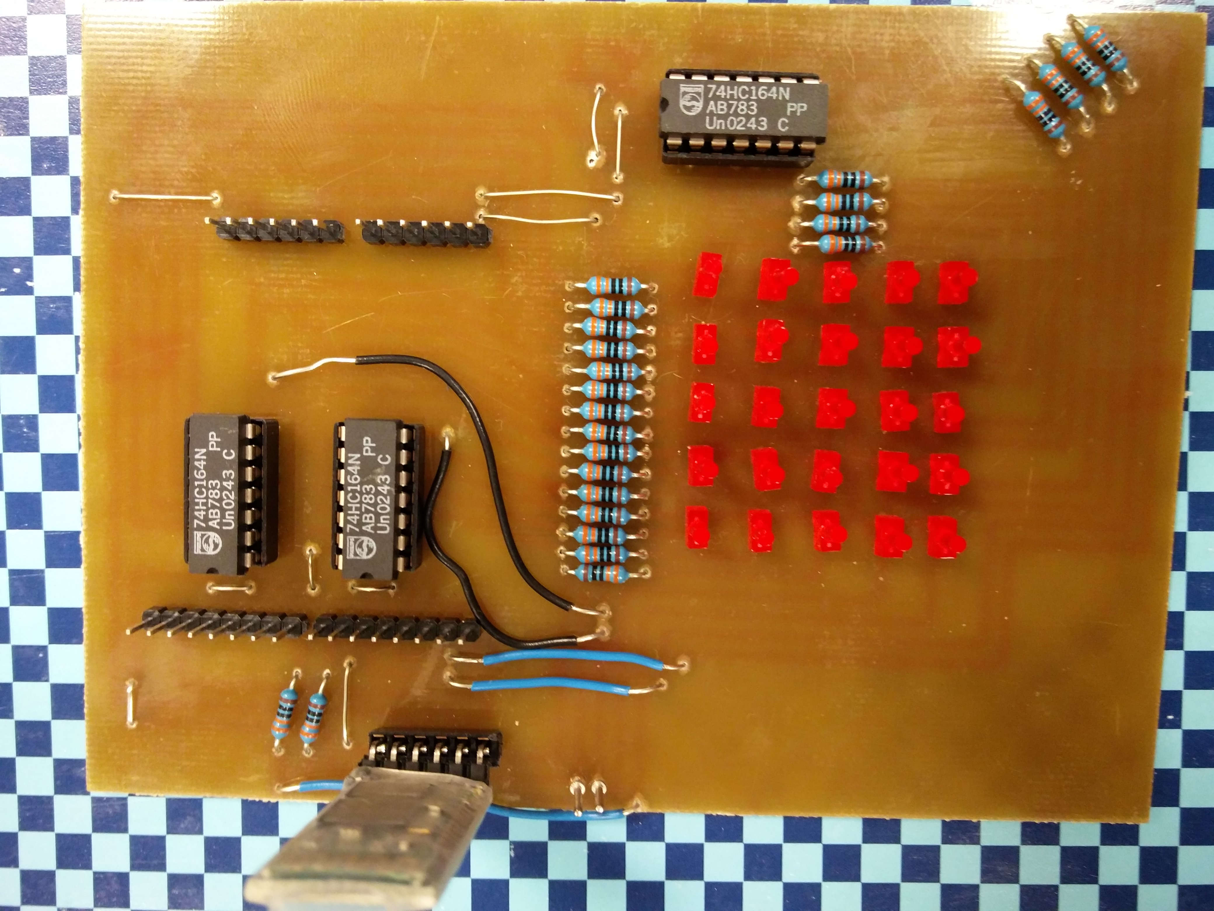
In hindsight, I probably shouldn't have placed the 5V and ground inputs so close to each other. Here's a picture of the finished PCB:
Software
The software consists of two components: the Arduino code and the Android app.
Arduino
The Arduino code is available here. The code needs to handle two things
simultaneously: Running the game of life and receiving commands over Bluetooth. Bluetooth
works by have the function serialEvent run every time new data is received via
Bluetooth. To avoid changes to the gol array while the next step is being computed, the
changes received via Bluetooth are stored in a separate array, and committed to the gol
array when the step computation has completed. This results in a loop function like the
one below:
void loop() {
  // if we are not paused, compute the next the game of life step
  if (!paused) {
    delay(750);
    gol_step();
  }
  // move changes from the changes array to the gol array
  // the changes array is updated in the handleSerialData function,
  // when a bluetooth command decides to update the board
  int i;
  for (i = 0; i < 25; ++i) {
    int x = i % 5, y = i / 5;
    if (changes[x][y] != 2) {
      gol[x][y] = changes[x][y];
      changes[x][y] = 2;
    }
  }
  // move the gol array to the array, which correctly maps coordinates to LEDs
  for (i = 0; i < 25; ++i) {
    set(i % 5, i / 5, gol[i%5][i/5] == 1 ? HIGH : LOW);
  }
  // actually update the LEDs
  write_config();
}
Bluetooth works by sending a stream of characters, so some method of marking the end of a
message is needed. In this project I've opted for delimiting commands with an exclamation
mark. The Arduino code accepts the command clr!, which clears the board, the commands
g 0! and g 1!, which pause and unpause the board, and [LED id] [0 or 1]!, which
turns a LED on or off.
Android
The Android code was written entirely by my partner in this project, so this section will be short. The android code is available here, and a picture of the app is shown below:

In order for the app to keep in sync with the Arduino, updates must be sent both back and forth. Updates are sent from the phone to the Arduino when the user interacts with the app, and the entire state is sent from the Arduino to the app when the Arduino computes the next the game of life step.
Imperfections
Unfortunately there are some imperfections present in this project. The main one has to do with the design of the circuit board. If you look at the Arduino code, you will see the following workaround:
// Stores the configuration of the board.
char configuration[27];
// maps a coordinate to an LED
int mapping[5][5] = {
  {26, 25, 24, 23, 22},
  {1, 0, 21, 20, 19},
  {3, 2, 18, 17, 15},
  {5, 4, 14, 12, 13},
  {7, 6, 11, 10, 9}
};
Notice how the configuration array has the length 27 instead of 25? Notice how the
mapping array doesn't have an entry for 8 and 16? These details are because the QH
outputs of the shift registers aren't connected to an LED, like the other outputs are.
Instead, they are just connected to the input of the next shift register.
This means that the Arduino has to control 3 LEDs directly, instead of just one.